


Download het artikel in ![]()
ENGINEERINGNET - A wide variety of blade designs are used and typically the blades cover about two thirds of the diameter of the reactor.
Where viscous products are handled, anchor shaped paddles are often used which have a close clearance between the blade and the vessel walls.
As with all equipment in the food and pharmaceutical industry, components of poor hygienic design may impair the quality of the products produced, as well as may compromise their safety for consumption.
Agitators and agitator shaft assemblies passing through the seals shall be designed and constructed to be smooth, with all surfaces meeting all the hygienic design criteria applicable to a product contact area.
Agitator ends shall have surfaces of minimum area immediately adjacent to the recipient ends and no longer than necessary to ensure proper incorporation of ingredients into a mix. The design of agitator product contact parts should minimize the occurrence of crevices, void spaces and dead spaces in grooves.
All voids should be closed by either fabrication (welding) or approved sealing techniques (O-rings, seals, etc.) to give surfaces ground flush and free of crevi-ces at points of metal-to-metal contact.
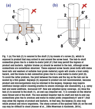
Metal-to-metal joints (e.g., keyways, hub-to-shaft joint, hub-to-end cap joint, etc.) may allow ingress and accumulation of product and/or microorganisms. (Fig. 1a and 1b).
Mounting of the impeller blades to the agitator shaft
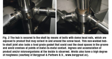
Preferably, the agitator shall be an all-welded one piece component (head photo), with all welds being ground flush and polished. Less suitable, not recommended designs are those in which hub, impeller blades and end nut are assembled together by screw joints (bolting) (Fig. 2).
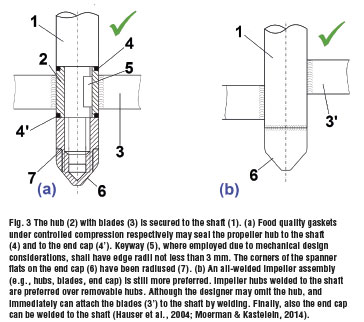
Debris may collect on exposed screw threads, even if bolts with dome head nuts and washers of suitable food grade material are used. Food quality gaskets under controlled compression may seal the propeller hub to the shaft and to the impeller nut (end cap) that secures the end of the agitator shaft (Fig. 3a).
Alternatively, the hub should be welded to the shaft and the end cap (Fig. 3b), with the blades of appendages (stirrers, homogenisers, mixers, etc.) welded to the hub. As an alternative to impeller blade-to-hub attachment, blades immediately can be attached to shafts by welding (without hub) (head photo).
Specific hygienic design requirements
Permanently joined metal surfaces with a total included internal angle less than 135° on agitators (e.g., at hubs and nuts) shall have a radius of not less than 3 mm tangential to both adjacent surfaces.
Corners (e.g., at hubs, nuts, spanner flats, etc.) must be radiused to facilitate cleaning, and horizontal areas must be sloped to prevent debris from becoming lodged on the surfaces and to allow for maximum drainabilty. Machined transitions such as shaft steps, coupling surfaces, spanner flats, etc. should have 15° to 45° sloped surfaces.
Impellers with flat, horizontal surfaces (e.g., flat-blade disc turbines, concave-blade disc turbines) may require additional design and/or cleaning practice to ensure drainage and cleanability, e.g., drain holes, spray ball and/or wand additions, increased CIP flow, adjusted spray coverage and faster impeller rotation.
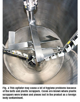
Where permanently installed agitators are equipped with an outer frame to which rubber, plastic or other similar scraping edges are attached, these scrapers shall be readily removable from the agitator.
They should be regularly checked for integrity. Cases are known where plastic scrappers were broken and pieces lost in the product as a foreign body contaminant. (Fig. 4).
Shaft connections
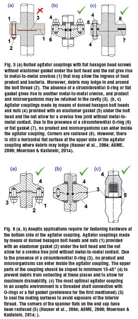
Welded in-tank shaft connections are preferred, although in-tank shaft couplings (Fig. 5a-c & Fig. 6a-b) and in-tank threaded shaft connections (Fig. 6c) are allowed if they are of acceptable hygienic design.
Threaded shaft connections are preferred over in-tank shaft couplings, although shaft rotation of the first is limited to a single direction to avoid that the shaft sections separate. The designer must ensure that the use of a threaded shaft connection is appropriate for the selected shaft diameter and design loads.
To avoided exposure of the threads to the product, O-rings or flat gaskets (preference for the first mentioned) should be used to seal mating surfaces (Fig. 6c).
Hygienic bolted coupling construction may be used where appropriate for the particular application. The preferred location for fastening hardware is on the underside of couplings, and the fasteners typically used should be hex-head cap screws, acorn-head cap screws and threaded studs with acorn nuts (Fig. 6a).
These fastener heads shall be free of raised or engraved markings that might inhibit cleanability. Again O-rings or flat gaskets (preference for the first mentioned) should be used to seal coupling mating surfaces. Elastomer seal washers (Fig. 5b-c & Fig. 6a) must avoid metal-to-metal contact .
Installation of agitators
Agitators permanently mounted are not required to be removable if they are readily accessible to be effectively cleaned via spray, directed flow, immersion or cleaning-in-place and if they do not interfere with drainage from the tank.
In kettles, however, it is recommended that the entire unit shall be constructed so that it can be tilted or lifted out of the kettle. When using an agitator, this should be preferably mounted on top of the tank, and if possible not in the center to limit the need of baffles inside the tank.
From a hygienic point of view, a shaft support frame at the bottom of a reactor should be avoided as much as possible. If this is not possible, e.g. because the shaft of a top entry agitator is very long, shaft supports must be mounted well clear of the base so as not to impede free draining of product and also so as to allow easy cleaning of their supports.
A longitudinal or helical groove may be cut in either the bush or the shaft. It should be deep enough to allow access into the bearing of either the product as a lubricant or the detergent for cleaning.
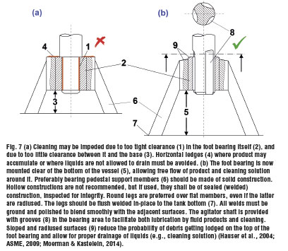
Sealed bearings can cause hygiene risks at their seals and should not be used in the product area. If, however, their use is unavoidable, their lubricants should be specified as being allowed with the food contact.
by Frank Moerman, KU Leuven & EHEDG Belgium
References
ASME (2009), Bioprocessing Equipment, ASME BPE-2009 International Standard, New York, United States, 213 p.
Hauser, G., Curiel, G.J., Bellin, H.-W., Cnossen, H.J., Hofmann, J., Kastelein, J., Partington, E., Peltier, Y. and Timperley, A.W. (2004), Hygienic Design of Open Equipment for Processing of Food, EHEDG Guideline N°13, 2nd edition, EHEDG subgroup ‘Design Principles’, EHEDG, Frankfurt, Germany, pp. 1-24.
Moerman, F. & Kastelein, J. (2014), ‘Hygiene design and maintenance of equipment’, Ch. 26, in Motarjemi, Y. & Lelieveld, H.L.M. (eds.), Food Safety Management: A Practical Guide for the Industry, San Diego, United States, Academic Press, p. 673-739.

