


ENGINEERINGNET.EU -- The vacuum pressure in several parts of the factory’s vacuum system is determined, firstly to evaluate the proper functioning of the vacuum pumping system, secondly to verify if the required ultimate pressure is attained and maintained (no leakage of air, and no virtual leaks due to out-gassing), and thirdly as a measure of safety to shut down the vacuum system in the event of malfunctioning.
The absolute vacuum pressure, which is the vacuum pressure measured relative to absolute perfect zero vacuum, at the vacuum process application is higher than the absolute vacuum pressure measured at the inlet of the vacuum source, due to pressure drop and because even vacuum components having a high conductance may create a pressure gradient.
Direct versus indirect vacuum measurement devices
Absolute vacuum pressure gauges are preferred over common non-absolute vacuum pressure gauges, because the latter are affected by changes in barometric pressure and elevation. There exist two kinds of vacuum pressure measurement gauges:
 Direct vacuum pressure measurement devices measure the pressure as the force which acts on an area. Gas particles exert a force through their impact on a wall, depending on the number of gas molecules per unit volume and their temperature but not on their molar mass. The reading of these measuring instruments is thus independent of the type of gas.
Direct vacuum pressure measurement devices are the liquid-filled vacuum gauges (open and closed manometer, and the McLeod gauge), the mechanical vacuum gauges (Bourdon and diaphragm gauge), and the electronic gauges (capacitive transmitters, liquid-filled capacitive transmitters). Table 1 gives an overview on the vacuum pressure measurement range of each of these direct vacuum pressure gauges.
With indirect vacuum pressure measurement devices, the pressure is determined as a function of a gas density dependent property, like thermal conductivity, ionisation probability, or gas friction. These properties are dependent on the molar mass as well as on the pressure.
The vacuum pressure reading of these measurement instruments depends on the type of gas, which means that the gas composition must be known to allow correct measurement. Indirect vacuum pressure measurement gauges are spinning rotor (viscosity and friction based) vacuum gauges, thermal conductivity vacuum gauges, ionisation vacuum gauges, etc.
 Limitations to vacuum pressure measurement
To reduce investment costs, selection of a vacuum pressure gauge that can measure over the whole vacuum pressure range found within the vacuum system would be the economical choice. However, there is no vacuum pressure gauge that can carry out quantitative measurements in the entire vacuum range.
Each vacuum pressure gauge has a characteristic measuring range, and the measurement uncertainty rises rapidly beyond the upper and lower limit of that range, making them inadequate to measure the vacuum pressure when exceeding these limits.
However, the applicable vacuum pressure measurement range of many of the techniques used to measure vacuums have an overlap. Hence, by combining several gauge types, it is possible to continuously measure system pressures from atmospheric pressure down to 10-11 mbar.
Measurement of pressures in the rough vacuum range (1013 down to 1 mbar vacuum absolute) can be carried out relatively precisely by means of direct vacuum pressure gauges. For measurement of vacuum pressures less than 1 mbar absolute, indirect vacuum pressure gauges with higher accuracy in that vacuum range are required. Notice that combining several different gauge types is often very expensive.
Liquid-filled vacuum gauges
Three well known liquid manometers are the open liquid manometer, the closed liquid manometer and the McLeod gauge. The term “manometer” is specifically used for liquid column hydrostatic pressure measurement instruments.
Open and closed liquid manometer
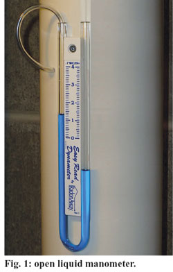
Liquid manometers consist of a cylindrical U-tube in glass partially filled with a liquid, usually mercury. However, almost any liquid can be used (e.g. water, heavy oil, etc.). One end of the U-tube is connected to the vacuum system, the other end can be either open or closed.
From the difference in the levels of the two columns, the pressure to be measured can be determined on the mbar scale provided. Open manometers (Fig. 1) measure vacuum pressure relative to local barometric pressure, and are therefore not very accurate. The closed manometer, however, is a simple and exact, low-cost vacuum pressure gauge for measuring pressure in the rough vacuum range (1013 down to 1 mbar), independent of atmospheric pressure.
Unfortunately, the use of this absolute vacuum pressure gauge in technical plants is limited because of its size and proneness to breakage. Moreover, if the gauge fluid is mercury (usually), it may also contaminate the process.

In general with liquid-filled vacuum pressure gauges, the working liquid may also evaporate if its vapour pressure exceeds the pressure within the vacuum system, and as such may contaminate the vacuum system. The use of very low vapour pressure oils instead of mercury may reduce that contamination risk, and they also may increase the sensitivity of a closed manometer.
McLeod gauge
The McLeod gauge is a compression vacuum gauge used for accurate measurements in an absolute vacuum range from 15 mbar down to 10-6 mbar. The pressure is measured by compressing a quantity of gas (that initially occupies a large volume) into a smaller volume by raising the mercury level.
The increased pressure obtained in this manner can be measured in the same way as in a U-tube manometer, and from that measurement the original pressure can be calculated. Today, the McLeod gauge is a rarely used vacuum pressure gauge, that is mainly applied as a standard in the calibration of other vacuum pressure gauges measuring in the medium to high vacuum range.
Notice that the McLeod gauge gives erratic response in the presence of water vapor, carbon dioxide, pump oil vapours, etc., because the high degree of compression causes condensable gas components (vapours) to condense.
As a consequence, the gauge rather will read the partial pressure of the non-condensables and the saturation vapour pressure of the condensate-mercury mixture instead of the total pressure. The resulting readings are erroneous, predicting a system pressure that is much lower than the true pressure.
The McLeod gauge is also slow, unsuitable for continuous monitoring, and - because of the presence of mercury - has the same disadvantages as the liquid manometers. Moreover, the McLeod gauge is not appropriate for pressure measurements in the vacuum range from 1013 mbar down to 15 mbar vacuum absolute.
Mechanical gauges
Mechanical vacuum pressure gauges measure the pressure directly by recording the force that the air/gas/vapour particles in a gas-filled space exert on a surface by virtue of their thermal velocity.
Bourdon vacuum gauge
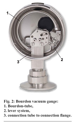
The first type of mechanical gauge is the Bourdon vacuum gauge (Fig. 2). A thin metal spiral tube is closed at one end and connected to the vacuum system at the other end. At the outside we find either normal atmospheric pressure or a defined absolute pressure, dependent on the model.
The inside of the tube is evacuated together with the vacuum system. Depending on the pressure difference between the inside and outside, the tube bends to a certain extent. By means of a lever system, the bend is transferred to a calibrated indicator needle and scale which displays the pressure of the vacuum system.
The pressure reading of the Bourdon vacuum gauge depends on the external pressure and is only moderately accurate (±2% of span) to approximately 10 mbar. However, high-precision Bourdon gauges are available that are as accurate as 0.1% of full scale.
Other Bourdon gauge types give their readings in absolute pressure because they combine two gauges in the same housing, a “pressure” gauge and a “reference” gauge connected by a ratio linkage that compensates for changes in the barometric pressure.
When the measured pressure is rapidly pulsing (e.g., near the vacuum pump), an orifice restriction in the connecting pipe is frequently used to avoid unnecessary wear on the gears and to provide an average reading.
When the whole gauge is subject to mechanical vibration, the entire case including the pointer and indicator card can be filled with an oil or glycerin. Bourdon gauges are less likely to contaminate the system than liquid-filled gauges.
Mechanical diaphragm gauges
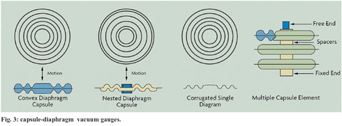
The second type of mechanical gauge is the mechanical diaphragm gauge. The diaphragm is a flexible disc, either flat or with concentric corrugations, made of sheet metal. Some gauges use the diaphragm itself as the pressure sensor; others use it as the basic component for a capsule manufactured by together fusion-welding of two diaphragms at their peripheries. There exist two types of mechanical diaphragm gauges:
In the capsule (diaphragm) vacuum pressure gauge, the pressure-sensing element is a hermetically sealed beryllium-copper capsule (Fig. 3) that has been evacuated to a pressure that is several orders of magnitude below the lower limit of the gauge pressure range. When the sealed instrument housing is attached to the vacuum system, the capsule expands, moving a pointer or pen by means of a mechanical linkage.
A capsule vacuum pressure gauge indicates the pressure on a linear scale independent of the external atmospheric pressure and the gas composition. Capsule vacuum gauges measure vacuum pressure accurately down to 10mbar but - due to the linear scale - they are least accurate at the low pressure end of the scale.
For accurate vacuum pressure reading below 50 mbar vacuum absolute, a differential diaphragm vacuum gauge is more suitable than a capsule diaphragm vacuum gauge. With a differential diaphragm vacuum gauge, the pressure scale is considerably extended between 1 and 100 mbar.
The interior in which the lever system of the gauge head is located, is evacuated to a reference pressure of less than 10-3 mbar and is separated from the vacuum (process) system by means of a corrugated diaphragm of special steel. During an evacuation procedure, the absolute vacuum pressure in the process system gradually decreases as compared to the reference pressure in the gauge head.
At first the diaphragm bends only slightly but then below 100 mbar starts to deflect to a greater degree. That diaphragm deflection is again transmitted to a pointer. In particular the measuring range between 1 and 20 mbar is considerably extended so that the vacuum pressure can be read quite accurately up to about 0.3 mbar vacuum absolute.
Notice that the sensitivity to vibration of this instrument is somewhat higher than for the capsule vacuum gauge.
In mechanical diaphragm gauges, the mechanical linkage has a high degree of hysteresis and dead-band, which limits their accuracy and repeatability. The accuracy of mechanical diaphragm gauges, in general, ranges from 0.2% to 2.0% of scale but dirt (e.g., processed material) in the gauges may compromise that accuracy.
To some extent, mechanical vacuum pressure gauges are also sensitive to vibration but in general small vibrations such as those that arise in the case of direct connection to a vacuum pump are not detrimental.
Electronic gauges
In electronic gauges, the pressure signal is converted into an electrical signal that can be transmitted, recorded, or displayed. The most commonly used electronic vacuum gauges to monitor vacuum pressures in (process) vacuum systems are the capacitance diaphragm gauge and the liquid filled capacitive transmitter.
Capacitance manometer (capacitance diaphragm gauge)
This is a vacuum pressure gauge in which the diaphragm makes up a part of a capacitor. A change in pressure leads to the flexure of the diaphragm, which results in a change in capacitance.
Capacitance manometers are rugged measuring devices, immune to contamination, because the gauge electronics never come in contact with the process. The only part in direct contact with the process is the diaphragm, that separates the reference cavity from the vacuum (process) system cavity.
The sensor body is usually fabricated from stainless steel or Inconel, while the diaphragm that is exposed to the process pressure on one side and to the reference pressure (usually very low vacuum) on the other side is made from stainless steel, high-nickel steel alloys (e.g., Inconel and Hastelloy, for corrosive service), tantalum (for highly corrosive and high temperature applications) or ceramic material with a vacuum-metalized coating.
Thin diaphragms can measure down to 10-5 mbar, while thicker diaphragms can measure in the low vacuum to atmosphere range. For all practical purposes, it is the only direct pressure measuring instrument that can measure absolute vacuum pressures under 1 mbar independent of the type of gas.
The use of variable-capacitance sensing increases the accuracy, repeatability, and sensitivity of diaphragm gauges by several orders of magnitude. Moreover, they exhibit excellent linearity over a wide range of pressures. The amount of voltage is directly related to the pressure. Accuracy under reference conditions is usually quoted as 0.25-0.5% of span.
Capacitance manometers are the best in terms of performance but are also the most expensive. However, they may be affected by changes in ambient temperature or the temperature of the gases flowing within the vacuum (process) system.
The effects of changes in ambient temperature or process-gas temperatures can be minimized through electronic compensation of a known temperature drift or by using sensor heaters to maintain the sensor at elevated temperature (typically 40 to 80°C). The influence of temperature can be further minimized through the use of ceramic diaphragm material.
 Liquid filled capacitive transmitters
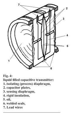
Liquid filled capacitive transmitters (Fig. 4) make use of a diaphragm seal. That diaphragm seal protects the sensing element of the capacitance manometer by placing a isolating diaphragm between the gauge sensor and the process media that it is measuring.
The cavity between the gauge sensing diaphragm and the isolating diaphragm is filled with a liquid. One side of the sensing diaphragm is evacuated and sealed to provide a reference for measuring absolute pressure.
As the measured pressure changes, the outside isolating diaphragm (also called process diaphragm) deflects slightly, shifting the position of the fill fluid. The fill fluid transmits the deflection of the process diaphragm to the sensing diaphragm.
Deflection of the sensing diaphragm is detected by capacitor plates positioned on either side of it. Signal conditioning converts the capacitance change to a stable dc voltage or current signal. Liquid filled capacitive transmitters are an excellent choice for most applications in the range 1013 mbar down to 1 mbar.
They are very rugged vacuum pressure sensors, because the most-sensitive components in the sensor are isolated from the process, and because movement of the process diaphragms is restricted to give overpressure protection.
by Frank Moerman, MSc., EHEDG Belgium
References:
Omega Engineering (1998),’Force-related measurements’, Vol. 3, Transactions in Measurement and Control, Putman Publishing Company and Omega Press, Stamford, United States, 83 p.
Roper D.L. & Ryans, J.L. (1989), ‘Select the right vacuum gauge’, Chemical Engineering, 96 (3), 125-144.
Umrath, W. et al. (2007), ‘Fundamentals of Vacuum Technology’, Cologne, Germany, 200 p.
Yoshimura, N. (2008), ‘Vacuum gauges’, Ch. 6, Vacuum Technology, Springer-Verlag Berlin - Heidelberg, Germany, p. 205-264.

