Vapours
Condensables and non-condensables on the vacuum inlet need to either pass through the pumps (if they are non-damaging), or need to be condensed.
To condense condensables into liquid, condensers or scrubbers are usually applied. The formed condensate is then drained. The presence of high condensable and non-condensable gas loads can significantly decrease the capacity of the vacuum system.

Even small quantities of both can take up large volumes. When a pump casing is full of liquid, the motor can become overloaded and the pump damaged. Moreover, if too much water vapours condense within the water ring pump, the temperature and hence the vapour pressure of the seal water will increase, giving rise to cavitation.
When the sucked air contains too much water vapour and condensables, a condenser is always required. In that case, the vacuum pump must not pass the condensate and the pump can be protected against too much condensate.

A condenser in front of a water ring pump is also useful to decrease the temperature of the air entering the pump, which allows to control the temperature and the vapour pressure at the pump inlet within acceptable limits so that cavitation is not likely. Notice that sucked air at higher temperature also can contain more moisture.
Condensers also prevent vacuum pumps from excessive contamination by reducing solid and liquid carryover, and from excessive concentration of corrosive vapours in the load. It is a general recommendation that the condensers should be cold enough to condense the vapours generated by the application, and that they should be of sufficient size to remove condensed liquid. If there is a condenser, a knock-out pot is often no longer a requisite. The vacuum pump can then be installed immediately after the condenser (Aglitz et al., 1995; Croll, 1998).
More than wet vacuum pumps, dry vacuum pumps cannot handle large amounts of water vapour or slugs of liquids, because they will shut or slow down, and the vacuum will be lost. Hence, a condenser ahead of the dry vacuum pump is highly recommended to keep up with air containing large amounts of water vapour.
That cold wall condenser prevents water vapour from entering and fouling the pump, and helps to lower the temperature of the air and gases drawn into the dry vacuum pump. The latter action prevents the dry vacuum pump from overheating (Myerson, 2000).
When a steam ejector is used to produce the vacuum, the same steam ejector can condense the water vapour as it is drawn along with the air from the vacuum application. Hence, a cold wall vapour condensor may not be needed except where a very high degree of efficiency is required.

Liquids
Liquid carryover can occur due to condensation in the vacuum pipeline leading to the pump, as the result of an upset condition, or along the exhaust system. That liquid may be responsible for a pump being stopped or damaged.
The problem becomes even larger if this liquid product solidifies in the pump. These deposits can prevent the pump to restart, demanding for disassembly and retiming, or can be responsible for damage to the pump's rotating components, requiring replacement.
To prevent that solid formation in the vacuum pump, it is best to have a barometric condenser, scrubber or trap that can remove these solidifying products from the vapour stream (Myerson, 2000).
To prevent liquid from getting into the vacuum pump inlet, a knockout pot, a water trap or a cyclone liquid remover is used. The type of separator required will depend upon whether there are slugs of water or small droplets of liquid entrained in the vapor stream.
Filtration is not an appropriate method to remove liquids from a vacuum inlet gas stream, because they usually just clog and cake filter media.
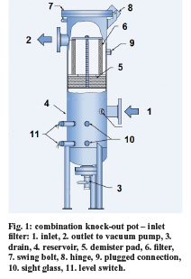
A knock-out pot (Fig. 1) serves to filter out entrained liquid droplets, slugs of liquid, aerosols, heavy mists and suspended solids from the vacuum air stream, to prevent them from entering the pump inlet. Sucked air that flows into the knock-out pot in a tangential way, can be stripped off these suspended solid particles and liquid.

For that purpose, knock-out pots may have special shell side baffling to ensure minimal pressure drop, non-condensable gas cooling, and separation of non-condensables and condensate. Usually the knock-out pot is also provided with a demister (mist eliminator) which removes mist, fog and aerosols, and which also acts as a pre-filter removing larger solid particles.
The housing of certain knock-out pots is designed as a cyclone in the area of the gas inlet, sometimes provided with baffles to create supplementary turbulences, and a jacket through which a cooling medium is circulated.
The tangential gas inlet and deflective cone force the incoming gas or vapour to flow along the vessel interior, decreasing their flow rate along the separating walls to give the condensables the time to condensate, and to separate off liquids and coarse particles.
The stripped gases are then diverted towards a filter cartridge that acts as a demister or a pre-filter. Once passed through these filter cartridges, the cleaned gas exits the knock-out pot through the gas discharge (Busch, K. GmbH, 2010a).
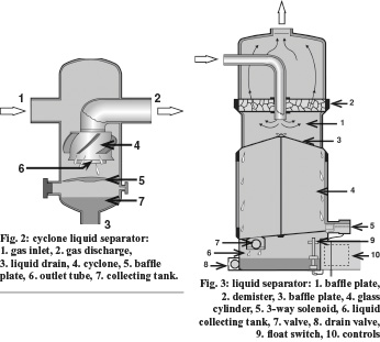
Cyclone liquid separators (Fig. 2) usually have no cooling jacket and a demister. The gas medium that usually contains less condensables (most of them are already condensed in an up-stream condenser) is subjected to turbulence when sucked in the separator.
The resulting centrifugal effect forces the liquid to the separating wall, where it then trickles down in droplet form to the collecting tank. The cleaned gas then leaves the cyclone through the outlet tube without passing a demister An alternative to cyclone liquid separators are liquid separators that make use of a demister (Fig. 3). (Busch, K. GmbH, 2010b & c).
Additional features are a collecting tank and condensate drain, sight glasses, high and low level switches and alarms, a lateral opening to clean the lower part of the knock-out pot, cyclone liquid separator or liquid separator with demister and a remo-vable top cover.
Removal of that lid makes it easier to inspect and clean the interior of the knock-out pot, and allows access to the filter cartridges (demister or fleece insert). Sometimes the final inlet filter to remove the smallest solid particles (10 µm) is installed just above the demister.
Solids
Nearly all vacuum pumping technologies have some degree of sensitivity to inlet particle contamination. Liquid ring, oil-lubricated rotary vane and all dry vacuum pumps need a particle filter on the suction side, ahead of the vacuum pump to protect the pump from considerable amounts of particle material and to extend its lifetime.
Even in front of a steam jet ejector a dust inlet filter can be required, because in certain vacuum processes producing varying amounts of solid carryover, that solid can deposit inside the ejector system and plug up the diffuser throat. If the potential for deposits exists, it is appropriate to install the steam jet ejectors in such a way that they are easily accessible for cleaning (Birgenheier, 1993).
The expected service life of a vacuum source comes down to how well it is protected from incoming contamination. Filters to protect a vacuum pump in a particulate environment against dust are available in many forms: paper filters, hydrophobic (water-resistant) synthetic fiber filters, fiber glass filter elements or metal mesh filters (Fig. 4).

Metal mesh elements are more appropriate than paper and synthetic fiber disposable elements, because they are generally easy to clean, are resistant to clogging, can be wetted without blocking and can tolerate high gas temperatures. The filter must be capable to efficiently trap the particles in the size range being generated (e.g., dust extraction systems) (Busch, K. GmbH, 2010d).
The filters should have at least the ability to retain 1-10 µm large particles. For very small particulates, special media such as HEPA (high efficiency particulate air) or ULPA (ultra-low penetration air) filters may be required. The particulate rate can be determined by calculating the volume of particulates per unit of time and by sizing the filter accordingly. It is also important to keep air flows below the recommended maximum velocity so that rated filtration efficiencies are maintained.
To increase the lifetime and dust holding capacity, “radial fine” elements with extensive surface area (Fig. 4) can be applied. An example of a small dust separator is given in Fig. 5. For very large chamber systems and high dust loads, a multi-bag type filter should be used. Especially cyclone liquid and dust separators (Fig. 6) are recommended for use in applications generating very high loads of larger particles, because they don’t clog and offer minimal impedance to gas flow.
Differential pressure gauges placed at the filter inlet and outlet can be used to determine filter saturation. A high pressure differential across the inlet filter results in a higher capacity requirement.
In simple terms, the vacuum pump has to create a deeper vacuum to account for the pressure drop across the inlet filter. If the vacuum pump capacity is fixed, the result will be a loss of vacuum at production equipment (Amos & Bruce, 2005; Bott, 2010; Busch, K. GmbH, 2010d).
Biological agents like spoiling or pathogenic microorganisms
Devices to minimize internal contamination of the vacuum pump with biological agents are disinfectant traps or HEPA filters installable in the vacuum line.
Each inlet in a process room to a vacuum system can be provided with a liquid disinfecting trap, to prevent microbial contamination of the vacuum line down-stream towards the vacuum source.
In view of the high risk of microbiological contamination, wet vacuum pumps must be capable of being sanitized.
(by Frank Moerman, MSc., European Hygienic Engineering & Design Group, Belgium, Pieter Van Hassel, Busch, Belgium)
References:
Aglitz, J., Bhatnagar, R., Bolt, D.E. & Butzbach, T.L. (1995), ‘Installing Liquid-Ring Vacuum Pumps’, Chemical Engineering, 102 (11), 132-138.
Amos, D. & Bruce, S. (2005), ‘Practical vacuum: good design, procedures and maintenance equals good vacuum’, Industrial Heating, 72 (5), 53-60.
Birgenheier D.B., Butzbach T.L., Bolt D.E., Bhatnagar R.K., Ojala R.E., Aglitz J. (1993), ‘Designing steam-jet vacuum systems’, Chemical Engineering, 100 (7), 116-121.
Bott, D. (2010), ‘Vacuum Pump Inlet Filtration’, AirBestPractices.com, 23-02-2010, 2 p.
Busch, K. GmbH (2010a), Combination knock-out pot/inlet filter, product leaflet, Maulburg, Germany, 1 p.
Busch, K. GmbH (2010b), Liquid separators for vacuum pumps, LSS/LSA 0100 - 0630, product leaflet, Maulburg, Germany, 2 p.
Busch, K. GmbH (2010c), Cyclone separators for vacuum pumps, CYC 0016 - 0630, product leaflet, Maulburg, Germany, 2 p.
Busch, K. GmbH (2010d), Liquid and dust separators for vacuum pumps, STF 0100 - 1000 & STA 0250 - 0630, product leaflet, Maulburg, Germany, 4 p.
Croll, S.W. (1998), ‘Keeping steam ejectors on-line’, Chemical Engineering, 105 (4), 108-112.
Myerson, E.B. (2000), ‘Effectively troubleshoot dry vacuum pumps’, Chemical Engineering Process, 96 (9), 49-58.


