


Download het artikel in ![]()
In many of today’s stringent processes, it’s becoming more and more recognized that system and process cleanliness is more critical than in previous years. Sensitive components (e.g., micro-electronics, pharmaceutical and food products) produced under vacuum may not become contaminated by the downstream vacuum source during its operation, shut-down or failure. The present article gives a better insight in which manner certain types of vacuum sources may contaminate the upstream vacuum process, and it provides the means to control and prevent backflow contamination.
Backflow contamination: why and how ?
Backflow contamination by steam and condensate from a steam jet
Where single- or multi-stage steam jets are used as vacuum source, check valves are rarely used. However, if the producer has to isolate and protect a water-sensitive process from a (series of) steam jet(s), a check valve in the suction line in front of the steam jet should be applied, to prevent steam or condensate from flowing back into the suction line in the event of steam jet failure. To completely isolate the steam jet(s) from the vacuum process, a manual control valve may be used. Steam jets are not damaged when a manual control valve isolates them from the upstream vacuum application (Birgenheier et al., 1993).
 Backflow contamination by oil liquid and vapour from an oil ring and oil rotary vane pump
Transfer of oil from an oil ring pump or oil-lubricated rotary vane pump’s inlet into the pumping line can occur due to several mechanisms:
The simplest way of backflow occurs whenever the pumping line stays under vacuum while the pump is shut off or fails. The pump may “suck-back”, bringing gases trapped within the pump or even air from atmosphere from the high-pressure side back through the pump. By this action, some of the pump oil may literally be forced into the pumping line (Mattox, 2009).
Additional liquid/vapour backstreaming occurs due to droplets of hot oil that can be physically flung from the pump’s inlet during operation due to mechanical breakdown of the oil films sealing the vane/body interface. Micro-bubbles of oil may also break on the surface, due to either the expansion of trapped light gases or the almost explosive expansion of condensed gases, such as liquid water which in hot oil can be converted into steam. When the bubble expands and breaks, the surface tension is such that the bubble explosively breaks down and imparts sufficient energy to the oil to allow it to leave the pump either as a liquid or vapour (Danielson, 1995 & 1999a).
However, direct oil vapour-state transfer from the oil ring pump or rotary vane pump to the chamber is the major source of oil contamination. When a pump operates continuously, the oil within the pump will become hotter and hotter (due to simple mechanical energy heat transfer) until some maximum temperature is achieved. This increase in oil temperature will result in an increase in oil vapour pressure, also determined by the quality of the oil. Un-distilled or poorly distilled oil will contain light fractions (low boiling components) which will volatize at low temperatures. A simple practical test is to sniff the inlet of a hot pump. If a fishy odour is detected, the oil is un-distilled or of poor quality. High quality, vacuum-distilled oil will be either odour-free or close to it, and should be of food-grade quality. Using a high quality oil will lower the risk for backsteaming of oil. Also notice that chemical breakdown of the seal oil can occur at high temperatures (Danielson, 1995 & 1999a).
Usually, a sliding vane pump is provided with a safety valve closing the suction side of the pump in case of power failure or standstill of the pump. In such a case, the pump is vented at the same time, so that it will not have to run against vacuum after re-starting. The effect of oil lubrication may be considered as the largest disadvantage of sliding vane pumps. Thanks to the installation of filters and automatic safety valves, the return flow of oil vapours from the pump into the vacuum vessel can be avoided to a great extent. Additionally, backstreaming traps of the condensation, absorbent or adsorbent type can be used. During their cleaning or regeneration, the captured oil may not be allowed to escape into the upstream side of the trap. Preferentially oil-sealed pumps should not be used to evacuate equipment containing sensitive products. Further, an oil ring pump may never run with a closed suction line (e.g., against a completely closed manual control valve), as cavitation and overheating may occur, resulting in damage and finally break down of the vacuum pump (Bannworth, 2005; Mattox, 2009).

Backflow contamination by process gas and seal water from a water ring pump
A check valve allows to isolate a water ring pump from the up-steam vacuum application, and to prevent backflow of process gas and seal fluid when the water ring pump is stopped or started-up. Only at standstill and start-up, a check valve closes. Vacuum sources operating in parallel on a common manifold must each have a manual or automatic shut-off valve, and a suitable check valve installed in the suction line close to the vacuum source. This allows each individual system to be isolated when it is not in operation (Bott, 2006).
A water ring pump may never run with a closed suction line (e.g., against a completely closed manual control valve), which causes cavitation and overheating, and will damage and finally break down the vacuum pump. If the possibility exists that the pump inlet can become closed during operation, it will be essential to install some type of vacuum relief valve (anti-cavitation valve) so that air can enter the pump inlet.
Means of backflow prevention
Check valves
Backflow of process gases, seal or motive fluid from the vacuum source into the pumping line back to the upstream vacuum application must be prevented by means of a check valve. On the exception of dry vacuum pumps where check valves are not really a requisite, all vacuum sources always should have check valves. Usually, dry-vacuum pumps only have a shut-off valve which closes whenever the dry vacuum pump for any reason is shut down. Dry vacuum pumps are not damaged when a manual control valve isolates them from the upstream vacuum application.
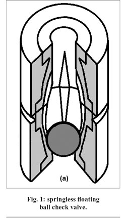
The use of ball-type check valves in vacuum circuits is the preferred practice. Check valves with springs, hinges and flappers should not be applied as they quickly become contaminated. With ball-type check valves, a cracking pressure of only 60 mbar is enough to unseat the ball (or poppet), so that a very small amount of flow can barely start. In vacuum circuits, it is recommended to use the following types of ball check valves:
Springless in-line floating ball check valves (Fig. 1) can be mounted vertically, with simply the weight of the ball or poppet holding it against its seat. This ball-type check valve is hydraulically highly efficient, with flow passing straight through vertically upwards. The in-line ball check valve is best used in applications where maintenance is infrequent. Its streamlined internal design reduces the potential for material to clog or hang up. If the flow reverses, gravity and the opposing line pressure will force the ball against the inlet of the valve, prohibiting any reverse flow.
When gas vapours enters the inlet of an Y-body ball check valve (Fig. 2), an elastomeric ball is pushed upward into the “Y” branch of the valve. When the gas flow stops, the pressure within the valve equalizes, and the ball will return from the “Y” branch of the valve, and rest itself against the smaller diameter of the valve near its inlet. Should a reverse flow situation occur, the opposing pressure of the fluid will seat the ball firmly against the inlet of the valve, preventing reverse flow.
It is recommended to install check valves in each branch line to every room or area to prevent any cross discharge.
Shut-off valves
Isolation (shut-off) valves are vacuum valves that separate two parts of a vacuum system from each other. Usually, they are not used as control valve. In example given, a shut-off valve can separate the vacuum pump from the vacuum process system, whenever this vacuum pump is shut down for extended periods of time or for maintenance procedures. As they have low pressure drops, knife gate, full-port ball and butterfly valves are recommended for that job. For larger piping diameters, ball valves become too expensive. As such, butterfly valves are then the more economical choice (Aglitz et al., 1995).
Observed from the vacuum application downstream to the vacuum source, the shut-off valve should be placed after the vacuum tank or knock-out pot, followed by the check valve as second protection valve, then a vacuum relief valve or a bleed valve (respectively to protect vacuum pumps with liquid seal against cavitation, or to flush or purge a dry vacuum pump), and finally an inlet filter just in front of the vacuum source.
Backstreaming prevention traps
Additionally, oil ring vacuum and oil-lubricated rotary vane vacuum pumps may be provided with a backstreaming prevention trap to prohibit migration of oil or its compounds from the vacuum source into the vacuum system. Installed between the inlet filter and the vacuum pump filled with seal oil, these anti-migration traps could be of the following types:
Condensation traps (cold traps) provide a cold surface that will condense the oil vapour onto the cold surface as a liquid or a solid. Its design can vary widely from a simple U-type pumping line stuck into a container of cold fluid to the more commonly used bucket design. Coolant media include water/ice, dry-ice slurries or liquid nitrogen. Oil vapour that enters the trap will impact upon the cold surface of the bucket, in example given filled with liquid nitrogen, whereupon it will condense as a solid. As liquid nitrogen gradually boils away inside the bucket, and escapes through a vent tube at the top of the trap, it must continuously be supplied to the reservoir through a fill tube. That filling may occur automatic when a liquid level sensor gives a signal. The consumption of liquid nitrogen is largely dependent on the level of vacuum maintained in the suction line, the frequency of vacuum cycling, the ambient relative humidity and the bleeding of gas. Regular regeneration of the trap is required, because condensable gas (such as water vapour) that enters the trap from the chamber will be co-condensed along with the oil vapours. The water vapour may freeze out as solid ice on the cold surface, and as such may hamper the trap’s performance. Regeneration may occur by warming the trap up to room temperature, while still under vacuum. However, then, the trapped material partially may enter the vacuum process equipment, which should be prohibited by providing a nitrogen gas flush from upstream while still pumping. Entire removal of the trap from the pumping line and off-line regeneration is still more appropriate (Danielson, 1999b).
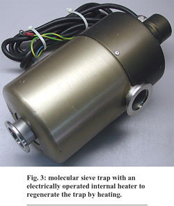
Absorbent traps (fig. 3) depend upon the property of a material to absorb oil vapour molecules and to retain them within the material’s body. A common design is composed of a replaceable stainless steel mesh cage filled with molecular sieve material that has a high specific surface area. That molecular sieve material performs a dual function. Firstly, the zeolite desiccant removes hydrocarbons which backstream toward the chamber when the mechanical pump oil is at its vapour pressure. Secondly, it also traps the water vapour and other gases discharged by an upstream vacuum process before they reach the mechanical pump where they can contaminate the pump oil. That latter pro-perty may help to significantly reduce the pump’s oil change frequency. The whole absorption process proceeds very well at or below room temperature. However, the absorption of water vapour by the zeolite is not always an advantage. In a system that is regularly cycled between vacuum and atmospheric pressure, the amount of water vapour pumped can saturate the zeolite long before it is saturated with oil. Most commercial molecular sieve traps are fitted with an internal heater to regenerate the trap by heating, while the trap is being pumped upon (fig. 3). Again a nitrogen gas flush upstream is then required to avoid any upstream migration of oil vapour during the in situ generation procedure by means of heat. Notice that molecular sieve material during these thermal expansion/contraction cycles will liberate fine dust that can enter the pump. There it may form with the pump oil an abrasive slurry that finally may cause wear within the pump. Moreover, if the trap is at atmospheric pressure, that fine dust also can be vented into a vacuum process (equipment) that is still under vacuum. Periodic replacement of the trapping sieve material when saturated is still the best way, and may occur through a port on top of the trap (Danielson, 1999b).
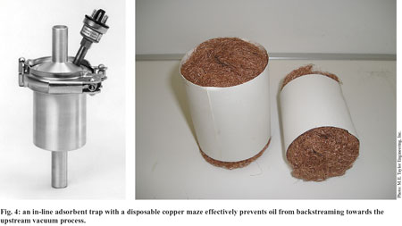
Adsorbent traps rely on the property of oleophilic surfaces to trap and hold oil molecules. Coaxial (or less recommended angle) metal sieve traps contain (removable) stainless steel screen cartridges filled with copper, stainless steel or bronze wools (fog. 4). During operation, backstreaming pump oil may coalesce on the elements and return to the pump, or hydrocarbons generated by a mechanical pump oil at its vapour pressure may adsorb on the filter materials. In single piece coaxial traps, the filter elements are permanently sealed inside the trap’s body and can’t be removed or replaced. These traps are serviced by replacing them with a spare unit while cleaning of the contaminated trap, usually with solvent, may occur. In two piece coaxial traps, the filter cartridges are quickly and easily replaced by removing the banded clamp that fastens the two-piece body. Other coaxial traps (non-metal sieve) are filled with activated alumina or active coal instead of metal wools. Activated alumina effectively adsorbs acids and water vapour, while activated carbon adsorbs organics and water vapour. Active carbon or alumina is not regenerated and reused. In general, adsorbent traps offer easy maintenance and room temperature operation. Due to their operating principle and off-line cleaning, they are the cleanest of all anti-migration traps. Because they don’t need cooling during their operation, or heating during their generation, they are also the cheapest ones (Danielson, 1999b).
Knock-out pot
A knock-out pot may also prevent vapours and related odours from being emitted back towards the vacuum process. Because a knock-out pot usually contains baffles and a jacket filled with cooling, it acts as such as a condensation trap and a adsorbent trap.
Frank Moerman, European Hygienic Engineering & Design Group
References:
Aglitz, J., Bhatnagar, R., Bolt, D.E. & Butzbach, T.L. (1995), ‘Installing Liquid-Ring Vacuum Pumps’, Chemical Engineering, 102 (11), 132-138.
Bannwarth, H. (2005), ‘Machines for vacuum generation’, Ch. 2, Liquid ring vacuum pumps, compressors and systems: conventional and hermetic design, Weinham, Germany, Wiley-VCH Verlag GmbH & Co. KgaA, pp.111-156.
Birgenheier D.B., Butzbach T.L., Bolt D.E., Bhatnagar R.K., Ojala R.E., Aglitz J. (1993), ‘Designing steam-jet vacuum systems’, Chemical Engineering, 100 (7), 116-121.
Bott, D. (2006), ‘Evaluate pressure drop in vacuum system’, PlantServices.com, 5 p.
Danielson, P. (1995), ‘Backstreaming from oil-filled mechanical vacuum pumps’, The Bell Jar, 4 (3), 3 p.
Danielson, P. (1999a), ‘Backstreaming from oil-sealed pumps’, Vacuum & Thin Film Magazine, July 1999, 3 p.
Danielson, P. (1999b), ‘Backstreaming traps’, Vacuum & Thin Film Magazine, Augustus 1999, 4 p.
Mattox, D.M. (2009), ‘Vacuum technology: Mechanical Vacuum Pumps’, Education Guide to Vacuum Coating Processing N°97, Albuquerque, United States, Society of Vacuum Coaters, p. 53-54.


