


Download the article in ![]()
ENGINEERINGNET.EU -- Properly designed and installed vacuum systems are less susceptible to fluctuations in production vacuum load, which can result in higher productivity, better-formed products and enhanced product quality or safety. As an example, in the semiconductor industry, oxygen from an air in-leak can chemically react with silane to produce sand, SiO2, not the desired semiconducting solid. In the food industry, improper vacuum during packaging may compromise the safety of the food product.
Design for airtightness
Vacuum lines must be completely airtight to guarantee their proper functioning to a maximum. Vacuum leaks in the piping components of the vacuum system could lead to insufficient vacuum capacity, and they also can allow non-condensable gases into the system as well as condensable contaminants. Even small quantities of both can take up large volumes, requiring higher-capacity vacuum sources, as well as bigger system components. An increase in the non-condensable load may also cause an unstable vacuum, because non-condensable loads must always travel through the vacuum source.

To minimize losses over the length of the suction line, the vacuum source should be installed in a technical corridor or mechanical room as close as possible to the process for efficient vacuum. Too long vacuum distribution lines increase the risk for air leaking within the vacuum system. The consequence is that the vacuum source must operate at an elevated level of vacuum to compensate for that leakage of air into the vacuum system. However, higher vacuum levels may open more leaks (Bott, 2006; Hesser, 2008).
Monitor for airtightness
Valves can be provided at several places in the vacuum line, to determine if air leakage occurs in the upstream piping of the vacuum system. However, too much isolation valves increase pressure drop. The most commonly used test methods to determine the presence of air leaks are the following:
• A pressure test with oil-free nitrogen allows to measure the decrease in pressure over a certain period of time (usually 24 h) in the entire system. Because leakage characteristics differ between a pressure-test and a vacuum operation, particularly in components, such as valves and flanges, pressure testing is only successful to find large leaks as it does not discover the small leaks that inevitably develop as the system ages (Umrath et al., 2007; Hesser, 2008).
• With the foam-spray test, the contractor can register the formation of bubbles in a soapy solution applied to leaking joints of a system under pressure (Umrath et al., 2007).
• In the «rate-of-rise» test, the entire system is lowered to a vacuum deeper than operating pressure, and the rise in pressure is monitored over a period of time. Given the system volume, leakage can then be calculated accurately. It is recommended to run this test on individual components of the system (piping, equipment, filters, knockout pots, etc.) as accurately as you can. The rate-of-rise over 24 hours for a given component of the vacuum system should be 10% or less of the operating vacuum absolute pressure (Fay et al., 2000; Hesser, 2008; Umrath et al., 2007).
• A vacuum test with a cream applied to all joints and potential leak points also is used to find air leaks. The cream will be sucked into the opening and the leak site will be easily observed.
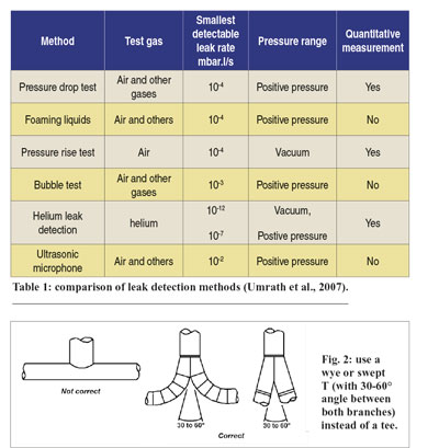
• During leak detection by means of a trace gas, helium is injected onto expected leaking parts of the vacuum system, after which the helium is allowed to enter and accumulate within that system for a period of time. Then the vacuum system is opened to the leak detector, and the helium-content is measured at the inside of the vacuum system (Senternovem, 2010).
• In ultrasonic detection, an ultrasonic detector is used to register the sound of in-leaking air. An ultrasonic acoustic detector can recognize the high-frequency hissing sounds associated with air leaks. Portable ultrasonic acoustic detectors consist of directional microphones, amplifiers, audio filters, and usually have either visual indicators or earphones to detect leaks. The principle behind ultrasonic leak detection is simple. In a vacuum leak, the leak flows from a high-pressure laminar to a low-pressure turbulent flow. That turbulence generates a noise which contains a broad spectrum of sounds ranging from audible to inaudible frequencies. An ultrasonic sensor focuses in on the ultrasonic elements in the noise. Because ultrasound is a short wave signal, the sound level will be loudest at the leak site. By generally scanning around a test area, it is possible to very quickly pinpoint the location of the leak site. The advantages of ultrasonic leak detection include versatility, speed, ease of use, the ability to perform tests while equipment is running, the ability to find a wide variety of leaks and its accuracy (Senternovem, 2010).
In table 1 a comparison is made between different air leak detection methods, more specifically their air leak detection potential.
Design for minimal pressure drop
Pressure drop is the difference between the vacuum level at the vacuum source inlet and the vacuum level at the end-use point. In rough vacuum, pressure drop in piping may not be larger than 50 mbar. In general, allowable pressure drop for piping systems is of the order of magnitude of 10% of the absolute vacuum pressure. This means that, for example, a 10 mbar vacuum system can tolerate only 1 mbar of line pressure drop. As depth of vacuum increases, the allowable pipeline pressure drop is proportionally less. If the system piping and equipment do not have an adequately-low pressure drop, then no matter how big the vacuum-generating device is, it can never achieve the desired level of vacuum (Fay et al., 2000; Senternovem, 2010).
Too long vacuum distribution lines are prone to higher pressure drops due to friction. But apart from too long pipe runs, inadequate (restrictive) vacuum piping diameter is also a major contributor to pressure drop. Proper pipe dimensions will help to limit vacuum fluctuations. As a rule of thumb, on single vacuum pump applications, the diameter of the vacuum pump inlet should be maintained as far into the process as possible. If the vacuum system has to be installed further away from the process, it is even recommended to oversize the vacuum line upstream of the vacuum source to minimize the overall line pressure drop. With increasing depth of vacuum, the vacuum line sizes increase. When several pump systems operate in parallel on a common manifold, the line size of the manifold should be minimal equal to the sum of the individual vacuum pump inlet cross-sectional areas (Bott, 2006).
With regard to pressure drop reduction, vacuum piping with smooth interior walls is superior to rough walled pipe. Further, the pipe parts to build the vacuum system should be rather long than short. Larger numbers of short pipes ask for more joints, increasing the risk for vacuum leaks. Piping runs should be as straight as possible. Every bend, every change in direction, etc. adds to pressure drop. Elbows should be kept to a minimum and, where they are necessary, long-radius elbows are preferable to 90-degree short-radius turns. Wherever two lines come together, to lower pressure drop, a wye or swept T (positioned horizontal, on their side) (Fig. 2) should be used instead of a tee (Bott, 2006; Hesser, 2008).
Adequate piping support should be provided to avoid liquids accumulating at low points of the pipe system and to minimize external loads on the vacuum source. But inversely, if not sufficiently supported, vibrations generated by the vacuum source also can cause air leaks in the upstream vacuum piping, if that piping is not sufficiently supported. Proper piping support also must intercept the external load caused by thermal movement (Fig. 2).
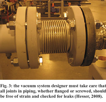
The vacuum system designer must take care that all joints in piping, whether flanged or screwed, should be free of strain and checked for leaks (Fig. 3). Improperly installed piping can result in misalignment, vacuum pump failure, and general operating problems. All piping connected to the vacuum source must be installed without imposing any strain on the system components. Vibration from the mechanical pump should be isolated from the vacuum system by means of flexible bellow connections that also allow corrections for misalignment. But because they are more prone to leakage, they should be kept short (Aglitz et al., 1995; Mattox, 2009).
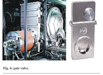
To minimize pressure drop, all piping between the process and vacuum source should have as few valves and fittings as possible, and all connections should be kept as short as possible. Isolation valves and check valves should be full-port and match the diameter of the system piping. The port diameters of standard ball valves are too restrictive for vacuum applications, and check valves may restrict the flow if they become lodged or fail to open completely. Full-port ball, gate (Fig. 4) or butterfly valves provide excellent flow characteristics with very little restriction, and also low-pressure drop check valves are available on the market (Bott, 2006).
Most vacuum pump technologies require inlet filters to remove particulates from the incoming air stream. A permanent low-pressure-drop strainer should be installed to save equipment and production downtime. Filter element loading increases pressure loss and can be easily avoided with proper preventive maintenance. Improperly sized filters with small port diameters also can be a major source of restriction. The filter manufacturer must check for proper sizing and installation (Bott, 2006).
At times it is necessary to use receivers and separators to remove liquids and solid particles from the vacuum air stream upstream of the vacuum pump inlet. It is important to have the correct type, configuration and porting on receivers and separators, to ensure adequate liquid separation and low pressure drop. Many separators have minimum and maximum velocity requirements for optimum separation efficiency. It is important to follow these guidelines to provide maximum protection for the vacuum pump (Bott, 2006).
Monitor for minimal pressure drop
That pressure drop can be measured by means of an accurate vacuum gauge. First, the vacuum level at the inlet of the vacuum source is monitored, and then the vacuum level at the point-of-use (or as close to the point-of-use) is measured with the same vacuum gauge (Bott, 2006).
Frank Moerman, European Hygienic Engineering & Design Group - Belgium
References
Aglitz, J., Bhatnagar, R., Bolt, D.E. & Butzbach, T.L. (1995), ‘Installing Liquid-Ring Vacuum Pumps’, Chemical Engineering, 102 (11), 132-138.
Bott, D. (2006), ‘Evaluate pressure drop in vacuum system’, PlantServices.com, 5 p.
Fay, T., Kraus, J.N. & Levy, M.J. (2000), ‘Improving vacuum systems’, Chemical Engineering, Vol. 107, (10), pp. 86-91.
Hesser, H. (2008), ‘Take the pressure off vacuum systems’, Chemical processing, 71 (2), 20-23.
Mattox, D.M. (2009), ‘Vacuum technology: Mechanical Vacuum Pumps’, Education Guide to Vacuum Coating Processing N°97, Albuquerque, United States, Society of Vacuum Coaters, p. 53-54.
Moerman, F. (2013), ‘Hygienic design of vacuum systems’, book chapter in progress, 23 p.
Senternovem (2010), ‘Vacuümsystemen’, brochure VNCI, Vereniging Nederlandse Chemische Industry, 8 p.
Umrath, W., Adam, H., Bolz, A., Boy, H., Dohmen, H., Gogol, K., Jorisch, W., Mönning, W., Mundinger, H.-J., Otten, H.-D., Scheer, W., Seiger, H., Schwarz, W., Stepputat, K., Urban, D., Wirtzfeld, H.-J., Zenker, H.-J., (2007), ‘Leaks and their detection’, Fundamentals of Vacuum Technology, Cologne, Germany, 200 p.

