


Download the article in ![]()
ENGINEERINGNET.EU -- These properties are dependent on the molar mass as well as on the pressure. As such the vacuum pressure reading of these measurement instruments depends on the type of gas, which means that the gas composition must be known to allow correct measurement.
Indirect vacuum pressure measurement devices are ionisation, heat loss and spinning rotor (viscosity and friction based) vacuum gauges. Table 1 gives an overview on the vacuum pressure measurement range of each of these indirect vacuum pressure gauges.
Main characteristics of indirect vacuum pressure gauges
Vacuum pressure measurements with indirect vacuum pressure gauges are extremely gas-type dependent, especially above 1 mbar. That gas-type dependency can lead to strongly incorrect readings for gases other than nitrogen, oxygen and air. Correction factors must be used for carbon dioxide, water and hydrocarbon vapours, etc. One must have knowledge of the gas composition but in practice that gas composition is known only as a rough approximation.
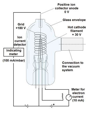
Figuur 1: hot-cathode vacuum gauge (Bayard-Alpert).
On the exception of the convection-enhanced Pirani vacuum gauge, all indirect vacuum pressure gauges only show reasonable accuracy below 1 mbar vacuum absolute, and even then their accuracy is not very high. Measurement errors are as high as 10-30% of the pressure reading in both the rough vacuum (> 1 mbar) and the medium/(utra)high vacuum range (< 1 mbar). The lack of accuracy using indirect vacuum pressure gauges is partially due to their sensitivity for contamination and the difficulties to clean them.
Ionization vacuum gauges
Ionization vacuum gauges, available since 1916, are the most important instruments for measuring gas pressures in the high and ultrahigh vacuum ranges. The gas whose pressure is to be measured enters the gauge head of the instruments and is partially ionized with the help of an electric field.
Ionization takes place when electrons are accelerated in the electric field and attain sufficient energy to form positive ions on impact with gas molecules. These ions transmit their charge to a measuring electrode (ion collector) in the system. The ion current, generated in this manner (or, more precisely, the electron current in the feed line of the measuring electrode that is required to neutralize these ions) is a measure of the pressure because the ion yield is proportional to the particle number density and thus to the pressure.
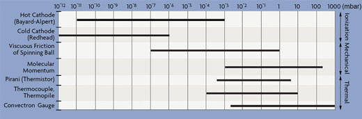
Table 1: Vacuum pressure measurement range of common indirect vacuum pressure gauges.
Under otherwise constant conditions, the ion yield and thus the ion current depend on the type of gas since some gases are easier to ionize than others. Ionization vacuum gauges are calibrated with nitrogen as the reference gas. To obtain the true pressure for gases other than nitrogen, the read-off pressure must be multiplied by the correction factor.
The two types available are the hot-cathode and cold-cathode gauge. Neither is particularly accurate or stable, and both require frequent calibration.
Hot-cathode gauges
Refined by Bayard-Alpert in 1950, the hot filament of the hot-cathode gauge (Fig. 1) emits electrons into the vacuum at a well-controlled, selectable rate. These electrons are accelerated towards a positively-charged wire grid (anode). On their passage into the space enclosed by the grid, the electrons collide with the gas molecules in the vacuum system and produce positive ions.
These positive ions are then accelerated towards and collected by the ion collector that is located along the axis of the cylindrical grid. The positively charged ions create a current in a conventional ion gauge detector circuit. The ion collector is at nearly ground potential, which is negative with respect to the grid.
At a constant filament-to-grid voltage and electron emission current, the rate that positive ions are formed is directly proportional to the density of molecules in the gauge for pressures below approximately 1?x 10-3 mbar. The strength of the ion current is then indicated on an electrometer that is calibrated in units of pressure. Hot-cathode gauges show high measurement stability because the emission current from the filament is controlled electronically to a constant value.
Most hot-cathode sensors measure vacuum in the range of 10-2 to 10-10 mbar. Newer instruments extend this range significantly by using a modulated electron beam, synchronously detected to give two values for ion current. At pressures below 10-3 mbar, there is little difference in the two values.
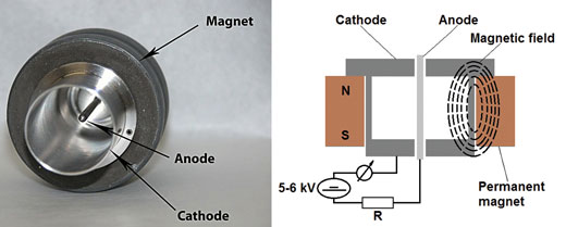
Fig. 2: Cold-cathode vacuum gauge.
At higher pressures, the ratio between the two readings increases monotonically, allowing the gauge to measure vacuums up to 1 mbar. Because most high-vacuum systems were made of glass in 1950, it made sense to enclose the electrode structure in glass.
Today, however, a modern vacuum system may be made entirely of metal. One argument in favour of this is that glass decomposes during routine degassing, producing spurious sodium ions and other forms of contamination. Nevertheless, glass gauges for the time being do remain the most popular hot-cathode sensors.
Cold-cathode gauges
Ionization vacuum gauges which operate with cold discharge are called cold-cathode vacuum gauges. A common feature of all types of cold-cathode ionization vacuum gauges is that they contain just two un-heated electrodes, a rod/probe-shaped anode and a cylindrical cathode, between which a so-called cold discharge is initiated and maintained by means of a d.c. voltage of around 2-3 kV (5-6 kV for Redhead cold-cathode gauges, Fig. 2) so that the discharge continues at very low pressures.
Electrons are drawn from the cathode surface by this high potential field and accelerated. The internal volume of the gauge is further penetrated by the magnetic field of a permanent magnet. The magnetic field is arranged such that the magnetic field lines of force cross the electric field lines.
In the Redhead design (inverted magnetron), this magnetic field around the tube deflects the electrons, causing them to spiral as they move across the magnetic field to the anode. This spiraling makes the paths of the electrons long enough so that the rate of their collision with gas molecules is sufficiently large, increasing the opportunity for them to encounter and ionize the present gas molecules.
So the magnetic field allows the formation of a sufficient number of positive and negative charge carriers that may move to the corresponding electrodes, resulting in a pressure-dependent discharge current, which is measured and indicated on the meter.
The measurement range of the Redhead-gauge is approximately 10-6 to 10-12 mbar. Under clean vacuum conditions, cold-cathode gauges are inexpensive, long-living (there are no filaments to burn out), unaffected by the inrush of air, relatively insensitive to vibration, easy to operate and low in maintenance. Attention should be paid to the drifting characteristics.
Initially, the pressure inside the gauge is often lower than in the vacuum chamber but after some operating time the gauge measures a higher pressure. So, there may be a relatively high degree of inaccuracy in the pressure reading (up to around 50 %), which also depends on the type of gas.
Thermal vacuum gauges
Heat loss gauges are absolute pressure gauges which are used extensively for medium vacuum measurement, and some types are also suitable for rough vacuum measurement. They are comparatively cheap, easy to install and have proven to operate successfully in a multitude of applications.
The basic principle uses the fact that the thermal conduction of the residual gas depends on its particle density and thus on the pressure. The characteristics of such gauges are not linear, instead they flatten to the lower and the upper measurement limits. Therefore accuracy and reproducibility fall off at the measurement limits.
In addition, the measurement is gas-type dependent, since different gases show different thermal conductivity coefficients. Heat loss vacuum gauges are usually calibrated for air or nitrogen. For use with other gases correction factors need to be applied.
Pirani gauge
Within the vacuum, a thin sensor wire within the head of the Pirani gauge (Fig. 3) is heated electrically as part of an adjusted Wheatstone bridge circuit. This current-carrying filament gives off its heat to the gas surrounding it, through radiation and thermal conduction. More or less energy is dissipated from the sensor wire depending on the residual gas density.
The heat transfer decreases the temperature and hence the resistance of the wire. The current through the sensing wire is increased to bring the sensing wire again to its initial resistance and temperature (approx. 150°C), and as such the current required to bring back the resistance and hence the temperature of the wire to its initial condition serves as a measure for the gas pressure.
The heating voltage which is applied to the bridge is controlled in such a way, that the filament resistance and thus the temperature of the filament remains constant regardless of the quantity of heat given off by the filament. The voltage across the bridge is also a measure of the pressure. The Pirani gauge is linear in the 10-2 to 10-4 mbar range.
Above these pressures, output is roughly logarithmic. A Pirani gauge will not work suitably to detect pressures above 1 mbar, because, above these pressures, the thermal conductivity of the gases no longer changes with pressure. From approx.
10 mbar upwards, uncontrolled convection effects further impair the accuracy and reproducibility increasingly. The thermal conductivity of each gas is different, so the gauge has to be calibrated for the individual gas being measured. Above
1 mbar the gas-type dependency increases and can lead to strongly incorrect readings for gases other than air or nitrogen. Pirani gauges are inexpensive, convenient, and reasonably accurate. They are 2% accurate at the calibration point and 10% accurate over the operating range.
Thermocouple vacuum gauge
In a thermocouple vacuum gauge (Fig. 4), two thin wires of different noble metals cross each other and are welded at the cross-point. This welded point forms a thermocouple. One of the wires is heated by means of a constant current of
20-200 mA d.c., and the thermocouple generates an output of about 20 mV d.c.
The resulting temperature of the thermocouple as well as its thermo-electrical voltage depends on the residual gas density. The heater wire temperature increases as the pressure is reduced, because less gas molecules are available that may dissipate the heat. Hence, the thermocouple gauge relates the temperature of the filament in the process gas to its vacuum pressure.
The thermo-electrical voltage is a measure for the vacuum. Typical thermocouple gauges measure between 0.001 mbar and approx. 20 mbar (absolute). This range can be increased by use of a gauge controller with a digital/analog converter and digital processing. Using an industry standard thermocouple sensor, such a gauge controller can extend the range of a thermocouple sensor to cover from 10-3 to 1.000 mbar, thereby giving it the same range as a convection-type Pirani gauge but at a lower price. Thermocouple gauges are robust and inexpensive but their error is the greatest.
Convection-enhanced Pirani vacuum gauge
Convection effects, which are problematic in the case of standard Pirani gauges, can be exploited in a defined way by means of a special sensor design. In convection-enhanced Pirani vacuum gauges (Fig. 5), a temperature-compensated, gold-plated tungsten sensor wire is mounted along the axis of a small tube which has to be installed horizontally. There are several physical effects that remove heat from this sensor wire. First, heat is removed from the sensor wire through the ends of the wire suspended in the vacuum region by the relatively large mass of the supports that attach the wire to the hermetically sealed electrical connections. Second, heat is removed from the suspended wire via conduction to the gas inside the transducer volume. Heat is also lost from the sensor by thermal radiation. Finally, for the convection enhanced Pirani-type transducer, heat transfer from the sensor is aided by convection currents of the gas at higher pressures inside the transducer volume.
The convection-enhanced Pirani gauge operates by maintaining a sensor wire at some constant temperature, and measuring the power required to maintain that temperature. If convection currents, gas conduction, thermal radiation and end-loss heat transfer characteristics are constant, a constant power level delivered to the sensor wire will keep the wire at a constant temperature.
If any of the physical effects change, the wire temperature will change. For example if the gas density and pressure around the wire is decreased, the wire will get hotter. If the gas density and pressure around the wire is increased, the wire will be cooled. By monitoring the amount of power required to the keep the sensor wire at a constant temperature, the pressure of the gas can be determined.
A thermal resistor wire coiled around the tube leads to an improved compensation of the ambient temperature in the bridge circuit, thereby extending the sensing range. At higher vacuums, response depends on the thermal conductivity of the gas, while at lower vacuums it depends on convective cooling by the gas molecules.
Both features together improve the accuracy and reproducibility of the gauge in the rough vacuum range (up to 1000 mbar) and also at the lower end of the measurement range. The measurement range is extended down to 10-4 mbar. However, the gas-type dependency of the measurement method remains. With the exception of its expanded range, features and limitations of this sensor are the same as those of Pirani and most thermocouple gauges.
Indirect mechanical vacuum gauges
In the process of measuring the pressure in a vacuum system, it is often important to avoid the introduction of high speed electrons and ions, hot ?laments, and other surfaces which may produce contamination. Also, in many cases it is essential that the pressure gauge does not change the composition of the gas, or introduce or remove gas from the system.
Indirect mechanical vacuum gauges are free of the above dif?culties, and at the same time they are capable of giving absolute values of the pressure when the composition of the gas is known. These instruments measure the deceleration of a rotor, caused by molecular friction and viscosity. At high vacuums, viscosity and friction both depend on pressure.
Viscous Friction gauge
Pressure-dependent gas friction at low gas pressures can be utilized to measure pressures in the medium and high vacuum range. In the viscous friction gauge (Fig. 6), the principle consists in determining the frictional torque produced by the gas or vapour on a spinning spherical rotor.
In technical instruments of this kind a steel ball with a diameter of several millimeters and magnetically suspended inside of the vacuum chamber without contact, is used as the measuring element. The ball is set into rotation through an electromagnetic rotating field and spun to the desired speed (around 425 Hz or 425 revolutions per second).
After reaching that starting speed, the ball is left to itself and allowed to coast freely. The rotational speed then drops at a rate that depends on the prevailing pressure under the influence and as a function of the viscous friction caused by the process vapours or gas molecules present.
If the friction introduced by the magnetic support is thus negligible in comparison with the gaseous friction and if the mean free path of the molecules is longer than the dimensions of the chamber surrounding the spherical rotor, then the gas pressure is derived from the relative decline of the speed f (slowing down).
The pressure of the gas (vacuum) is thus determined by measuring the length of time it takes for the ball to drop from 425 to 405 revolutions per second after drive power is turned off. The deeper the vacuum, the lower the friction and therefore the more time it will take to reach the lower rotational speed.
This gauge may measure vacuums down to 10-7 mbar. When calibrated this design is accurate to as low as 1.5% of the reading, while uncalibrated the uncertainty is 4% or more. Since its wetted parts are made of stainless steel, the gauge is suitable for corrosive services. It is also suited for operation at temperatures up to 4150°C.
Molecular Momentum gauge
Molecular momentumtype gauges have two basic working parts: a rotating and a restrained cylinder. The gas molecules in the process sample come in contact with the rotating cylinder (rotor spins at a constant speed of 3600 rpm), experience a momentum change, are set in motion in the direction of rotation and propelled into the restrained cylinder.
The gas molecules acquire thus energy from contact with the spinning cylinder, and then, in turn, strike and transfer that energy to the restrained cylinder. On collision, the gas molecules drive the restrained cylinder to a distance proportional to the force of impact and energy transferred, which is a measure of the number of gas molecules in that space. The number of molecules is related to the absolute pressure of the gas.
The pointer attached to the restrained cylinder indicates the gas pressure on the scale. The energy transferred in momentum transfer gauges is not just related to the number of molecules (pressure) and the velocity of molecules; the molecular weight of the gas is also a factor. Thus, the full-scale range of the gauge depends on the type of gas being measured.
For air, the range is (2.7 to 1.3 10-3 mbar), while for hydrogen, the maximum reading on the instrument is 37 mbar. Thus, molecular momentum transfer vacuum gauges have to be calibrated for each application. They give continuous direct readout, but are not usually available as a signal transmitter for remote indication or control.
The inaccuracy of the unit is between +/- 5 and 25%, with accuracy decreasing at lower pressures. Additional inaccuracy can be caused by process temperature variations, which in the range of 28 to 56°C, can amount to 2%. External vibration in the range of 50 cps should be protected against by the use of bellows couplings on the process connection. The gauge is not damaged by exposure to atmospheric pressure, but the sample from the process has to be kept clean, free of dust, oil, or other particles.
by Frank Moerman, MSc., EHEDG Belgium
Sources:
Lipták, B.G., Welch, J. & Gilbert, R.A. (2003), ‘Vacuum sensors’, Ch. 15, section 15.14, in Lipták, B.G. (ed.), Instrument Engineer’s Handbook, 4th edition, Process Measurement and Analysis, Vol. 1, CRC Press LLC, Boca Raton, Florida, United States, pp. 795-806.
Omega Engineering, Inc. (1998), ’Force-related measurements’, Transactions in Measurement and Control Series, Vol. 3, Putman Publishing Company and Omega Press LLC, Stamford, United States, 83 p.
Pfeiffer Vacuum (2009), ‘Vacuum Technology Know How’, Asslar, Hessen, Germany, 159 p.
Umrath, W., Adam, H., Bolz, A., Boy, H., Dohmen, H., Gogol, K., Jorisch, W., Mönning, W., Mundinger, H.-J., Otten, H.-D., Scheer, W., Seiger, H., Schwarz, W., Stepputat, K., Urban, D., Wirtzfeld, H.-J., Zenker, H.-J., (2007), ‘Fundamentals of Vacuum Technology’, Cologne, Germany, 200 p.
Yoshimura, N. (2008), ‘Vacuum gauges’, Ch. 6, Vacuum Technology, Springer-Verlag Berlin - Heidelberg, Germany, p. 205-264.

