


Download the article in ![]()
ENGINEERINGNET.EU -- Pressure gradients in the vacuum system may be observed because of air leaks and poor conductance of vacuum system components. An accurate vacuum readout simplifies the job of locating various system malfunctions.
For proper functioning, the vacuum pressure measurement devices must be correctly calibrated, appropriately located and installed in a manner that pressure readings are not falsified. This article also considers the hygienic requirements that vacuum pressure measurement devices must meet for sensitive applications in critical environments (e.g., food and pharmaceutical industry).
Installation of a vacuum gauge at specific points to monitor malfunctioning
A vacuum gauge at a vacuum pump’s inlet and immediately in front of the pump is required to verify the suitable functioning of the vacuum pump and to measure if the pump generates sufficient capacity and the required appropriate ultimate vacuum pressure in the suction line. The vacuum gauge at the vacuum pump’s inlet should be placed so that it is not easily contaminated by back-streaming.
If the intake gauge reading is lower than the established working level, then either the pump is not working properly or there is a leak somewhere in the system. Valves can be provided at several places in the vacuum distribution system to determine if an air leakage occurs in the upstream located vacuum system.
If there is a leak in the vacuum distribution system between vacuum application and blocking valve, blocking the line will restore the vacuum measured by the gauge positioned in the downstream line section towards the vacuum source and behind that valve.
Then, by moving the block further and further towards the vacuum application, the trouble spot can be pinpointed. Additional gauges elsewhere in the system can simplify the identification of various system malfunctions (e.g, leaks) but notice that the reading, if the suction line vacuum gauge is located elsewhere in the system, may be inaccurate because of dirty or clogged filters, kinked vacuum lines, closed valves, or other problems.
Other vacuum gauges also should be located at the room control valve or close to the process vacuum equipment to monitor the process vacuum system. Positioning a vacuum gauge at the same height of the process equipment under vacuum is not recommended, because the vacuum gauge may become contaminated, giving raise to incorrect vacuum pressure readings or unhygienic conditions in the food or pharmaceutical contact area. The vacuum gauge shall be placed in the evacuation or vapour line just beyond the product contact surface.
Installation to avoid falsified pressure readings
Measures to eliminate temperature effects
The external housing must be checked for sufficient temperature decoupling from the vacuum (process) system. Sources of intense heat radiation or sources of cold which generate an ambient temperature around the measurement system which lies respectively above or under the specific acceptable temperature operating range of the vacuum gauge must be avoided.
Vacuum gauges may be affected by changes in ambient temperature or the temperature of the gases flowing within the vacuum (process) system. If the vacuum (process) system or lines have too warm, the effects of changes in process gas temperatures can be minimized by means of a cooling element (Fig. 1 (see top)), a diaphragm seal with capillary tubing for remote mounting, a siphon, a loop seal or by purging.
Loop seals and siphons are less hygienic solutions. Alternatively, the gauge housing can be cooled electrically (Peltier effect) or by means of water. If the vacuum (process) system or lines have too cold, sensor heaters may keep the sensor at elevated temperature (typically 40 to 80°C).
If there is downward temperature drift due to the vacuum process system being frozen, freeze protection may occur by means of steam tracing or resistance heating (electronic compensation) in combination with thermal insulation. If a diaphagm seal is used, the oil filling in the diaphragm seal housing not only may prevent humid ambient air to enter the vacuum gauge but it also may prevent a cold vacuum (process) fluid from freezing any condensate within the gauge.
Measures to eliminate poor conductance effects affecting accurate pressure readings
An error frequently made when connecting vacuum pressure measurement sensors to a vacuum (process) system is the use of connector piping which is unacceptably long and narrow.
Long and narrow pipe connections show reduced conductance of the pipe connection, resulting in either a too slow evacuation of the connector line so that the indicated pressure is too high, or in a too slow venting to atmosphere of the pipe so that the indicated pressure is then too low.
With low conductance connector lines, measurement errors by more than one complete order of magnitude are possible. Wrong vacuum pressure readings are also observed if the pipe connection is narrowed due to its contamination with debris or its obstruction with liquid.
Measures to eliminate pressure misreadings due to contaminants
Pressure measurements may become falsified, especially for all types of vacuum gauges whereby high-sensitivity and high-accuracy measurement systems are particularly susceptible to soiling. However, fundamentally, it is nearly impossible to prevent the measurement system in a vacuum gauge from becoming soiled.
Also considerable quantities of continuously or intermittently liberated process gases or vapours may pass into the pressure measurement system, where they may damage and destruct the vacuum pressure sensing mechanisms due to condensation, corrosion or deposition of contaminants. Especially into mechanical gauges, delicate links, pivots, and pinions are sensitive to condensation of water vapour.
That water condensate, in colder climates, may even freeze and damage the gauge housing. Measures should be taken to ensure that the influence of contamination on pressure measurement remains as small as possible.
Sensors should only be installed inclined upwards with the vacuum flange at its bottom to keep condensate, debris, suspended solid particles, flakes, etc. from clogging the sensor port or from falling into the sensor and the measurement system.
The user of the gauge can attempt to protect the measurement systems against contamination by providing suitable shielding but this solution often leads to pressure readings by the measurement system – although clean – that deviate considerably from the pressure actually prevailing in the system.
Cleaning the measurement system is another solution but certain vacuum gauges (e.g., liquid-filled gauges, mechanical vacuum gauges, convection-enhanced pirani, etc.) are too fragile to be cleaned.
Measures to eliminate vibratory effects
Install vacuum gauges at those points in the vacuum system that will remain free of vibration during operation, because liquid-filled and mechanical gauges are prone to failure by vibration. Glass tubes of the liquid-filled vacuum gauges may break, and the delicate links, pivots, and pinions of the mechanical gauges may become damaged.
Pulsation dampeners can help to absorb pressure shocks and average out pressure fluctuations. To dampen pointer vibration and gauge lifetime, the pointer gauge housing can also be filled with a viscous oil (Umrath et al., 2007).
Measures to eliminate the effect of magnetic fields and electrical potentials
Too long measurement cables (connector cables between the sensor and the vacuum gauge control unit) should be avoided because strong interfering magnetic leakage fields or electrical potentials can falsify vacuum pressure measurement. Wireless transfer of data between vacuum measurement instrumentation and control equipment is highly recommended.
Installation for hygiene
Sanitary installation of vacuum gauges
Most pressure instruments (gauge, switch, transducer, or transmitter) are designed without sanitary process connections. However, connector threads on a standard sensor provide a space where bacteria could grow.
The use of sanitary process connections, free of crevices, threads, metal-to-metal contact, etc. to install vacuum gauges on piping and vacuum equipment processing sensitive food or pharmaceuticals should occur in agreement with EHEDG guideline documents N° 10, 16 and 37. Typical hygienic connections are DIN 11864 A & B, Neumo Bioconnect®, Varivent®.
Diaphragm seal
As an alternative, a diaphragm seal may avoid the vacuum gauge port from plugging up with debris, liquid condensate, etc., and it protects the sensing element of the gauge by placing a isolating diaphragm between the gauge sensor and the process media that it is measuring. In example given, corrosive and noxious process materials are prohibited from reaching the dead-ended sensor cavity.
Vice versa, diaphragm seals (or gauge guards) may also protect the process. Notice that process fluids that have accumulated in the pressure port or the dead-ended sensor cavity of vacuum gauges without diaphragm seal may compromise the physical and microbiological integrity of the process fluid.
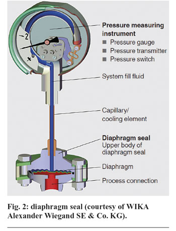
Further, certain metals in the electronic pressure sensor may contaminate the fluid with lead, zinc, copper, cadmium, etc. Mechanical gauges always require a diaphragm seal for proper hygienic installation (Fig. 2).
A diaphragm seal is composed of three main parts:
Housing containing the process and sensor connections for the diaphragm seal, and the fill fluid.
Isolating diaphragm, a flexible membrane that separates the mechanical or electrical sensing element and fill fluid from the process material, and allows pressure effects to cross from the vacuum (process) system through the isolating diaphragm to the fill fluid and finally to the sensor’s measuring element.
Isolating diaphragms with a thickness of approximately 3 mm are made of food process compatible materials such as plastics and rubbers (moderate rough vacuum levels), or metal plate (deeper rough vacuum levels). Metal diaphragms of stainless steel (several grades), hastelloy, monel, inconel, tantalum, titanium and several metals should be welded flush to the housing.
Capacitive sensors consist of a ceramic diaphragm of Al2O3 that is separated from the metallic sensor body via an elastomer seal, the design of which must be considered carefully as there is a risk of pores.
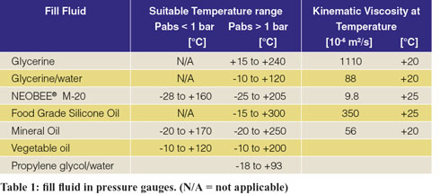
Fill fluid (in the cavity between the gauge sensing and the isolating diaphragm) is application specific, which means that it varies for food, beverage or industrial applications. In food applications, a stable, food-grade, non-corrosive, low thermal expansion and low viscosity fluid should be used (Table 1).
For high temperature applications, a sodium-potassium eutectic is commonly used; while a mixture of glycerine and water is preserved for ambient temperatures, and ethyl alcohol or silicon oil are applied for low temperatures. Water-based glycerine is not an appropriate fill fluid in hard-vacuum and high-temperature applications due to its risk of vaporization, which can destroy the diaphragm seal.
At low temperatures, the water-based glycerine becomes too thick to produce accurate readings due to the extremely slow response time.
Hygienic design of vacuum gauges
The casing of vacuum gauges should preferably be made of austenitic stainless steel AISI 304, 316, 316L, etc. or sanitary plastic, and should be watertight to protect against cleaning agents. The outside, non-product contact area of the casing may have a roughness Ra > 0.8 µm if test results have shown that the required cleanability is achieved.
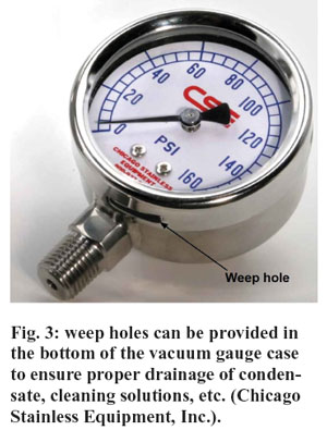
Weep holes (Fig. 3) can be provided in the bottom of the case to ensure proper drainage of condensate, cleaning solutions, etc. The types of glass used as gauge window or gauge tube should be carefully evaluated with regard to crack risk and sensitivity to corrosion, as hydrolysis especially at higher temperatures and pH values may occur.
Polycarbonate (PC), poly(methyl methacrylate) (PMMA) and polysulfone (PES) are the most commonly used materials for sanitary gauge windows (Höhler et al., 2007).
To avoid build-up of pathogenic and spoiling microorganisms and/or to prohibit the formation of biofilms, product contact surfaces (e.g. metallic diaphragm) should be free of microscopic faults and electropolished to a surface finish of 0.8 µm Ra, or better. Wetted surfaces should be fully drainable.
When in contact with process media, they need to be passive and free of pits and crevices, to reduce the likelihood of unwanted particles adhering to these surfaces.
The housings of electronic pressure instrumentation (transducers, transmitters, switches, etc.) are often full or partially made of plastic, that should be stress crack-resistant, resistant to cleaning agents and disinfectants, and possess high hydrolytic stability in the presence of hot water and steam.
External housing and wiring may not collect dust or soil, and must be easily cleanable and self-drainable. The recommended ingress protection rating for electronic pressure instrumentation in the food industry should be IP65 or better but when exposed to CIP or SIP an ingress protection rating of IP67 or better is required.
Calibration of vacuum gauges
Without exception, vacuum gauge and vacuum pressure sensors require scheduled, periodic maintenance and/or recalibration. Pressure transducers can be recalibrated in a calibration laboratory or on-line.
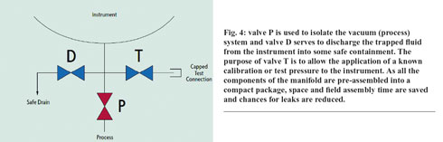
Laboratory recalibration typically is preferred but often is not possible or necessary. However, it is recommended that the vacuum pressure measuring instrument can be removed from the vacuum (process) system without shutting down the (process) vacuum system. A three-way manifold (Fig. 4) can provide such a protection.
Frank Moerman, MSc., European Hygienic Engineering & Design Group - Belgium
References
Cole-Parmer (2009), ‘The Sanitary Instrumentation Primer: keeping your process application contamination-free, Illinois, United States, 12 p.
Höhler, A., Schumacher, B., Schrodt, T., Bühler, H., Nalbach, U., Gasparetti, M., Wössner, S. (2007), ‘Hygienic Design and Application of Sensors’, EHEDG Guideline N° 37, EHEDG subgroup Sensors, EHEDG, Frankfurt, Germany, pp. 1-35.
Moerman, F. (2013), ‘Hygienic design of vacuum systems’, book chapter in progress, 23 p.
Omega Engineering (1998),’Force-related measurements’, Vol. 3, Transactions in Measurement and Control, Putman Publishing Company and Omega Press, Stamford, United States, 83 p.

